-
Drawing Ray Diagrams
Representation of Images Formed by Spherical Mirrors Using Ray Diagrams
We can also study the formation of images by spherical mirrors by drawing ray diagrams. Consider an extended object, of finite size, placed in front of a spherical mirror. Each small portion of the extended object acts as a point source. An infinite number of rays originate from each of these points. To construct the ray diagrams, in order to locate the image of an object, an arbitrarily large number of rays emanating from a point could be considered. However, it is more convenient to consider only two rays, for the sake of clarity of the ray diagram. These rays are so chosen that it is easy to know their directions after reflection from the mirror.
The intersection of at least two reflected rays gives the position of the image of the point object. Any two of the following rays can be considered for locating the image.
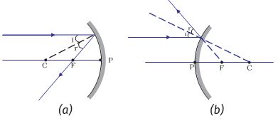
1. A ray parallel to the principal axis, after reflection, will pass through the principal focus in case of a concave mirror or appear to diverge from the principal focus in case of a convex mirror. This is illustrated in Fig.10.3 (a) and (b).
Figure 10.3
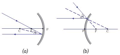
2. A ray passing through the principal focus of a concave mirror or a ray which is directed towards the principal focus of a convex mirror, after reflection, will emerge parallel to the principal axis. This is illustrated in Fig.10.4 (a) and (b).
Figure 10.4
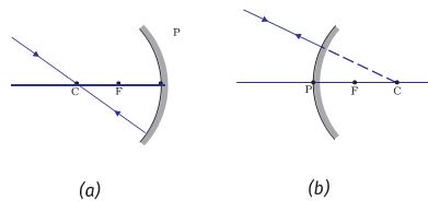
3. A ray passing through the centre of curvature of a concave mirror or directed in the direction of the centre of curvature of a convex mirror, after reflection, is reflected back along the same path. This is illustrated in Fig.10.5 (a) and (b). The light rays come back along the same path because the incident rays fall on the mirror along the normal to the reflecting surface.
Figure 10.5
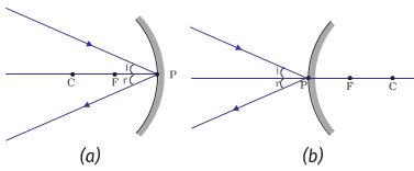
4. A ray incident obliquely to the principal axis, towards a point P (pole of the mirror), on the concave mirror [Fig. 10.6 (a)] or a convex mirror [Fig. 10.6 (b)], is reflected obliquely. The incident and reflected rays follow the laws of reflection at the point of incidence (point P), making equal angles with the principal axis.
Figure 10.6
Remember that in all the above cases the laws of reflection are followed. At the point of incidence, the incident ray is reflected in such a way that the angle of reflection equals the angle of incidence.
-
Image formation by Concave Mirror
Image formation by Concave Mirror
Figure 10.7 illustrates the ray diagrams for the formation of the image by a concave mirror for various positions of the object.
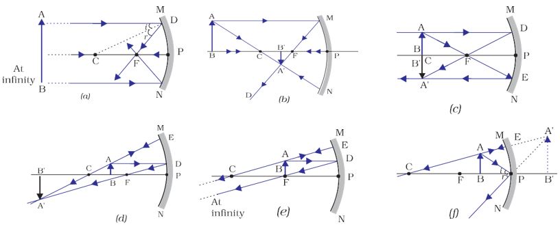
Figure 10.7 Ray diagrams for the image formation by a concave mirror
Activity 10.4
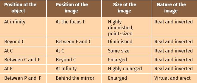
Draw neat ray diagrams for each position of the object shown in Table 10.1.
Table 10.1
You may take any two of the rays mentioned in the previous section for locating the image.
Compare your diagram with those given in Fig. 10.7.
Describe the nature, position, and relative size of the image formed in each case.
Tabulate the results in a convenient format.
Uses of concave mirrors
Concave mirrors are commonly used in torches, search-lights, and vehicle headlights to get powerful parallel beams of light. They are often used as shaving mirrors to see a larger image of the face. The dentists use concave mirrors to see large images of the teeth of patients. Large concave mirrors are used to concentrate sunlight to produce heat in solar furnaces.
-
Image formation by Convex Mirror
Image formation by Convex Mirror
We studied the image formation by a concave mirror. Now we shall study the formation of image by a convex mirror.
Activity 10.5
Take a convex mirror. Hold it in one hand.
Hold a pencil in the upright position on the other hand.
Observe the image of the pencil in the mirror. Is the image erect or inverted? Is it diminished or enlarged?
Move the pencil away from the mirror slowly. Does the image become smaller or larger?
Repeat this Activity carefully. State whether the image will move closer to or farther away from the focus as the object is moved away from the mirror?
We consider two positions of the object for studying the image formed by a convex mirror. The first is when the object is at infinity and the second position is when the object is at a finite distance from the mirror. The ray diagrams for the formation of image by a convex mirror for these two positions of the object are shown in Fig.10.8 (a) and (b), respectively.
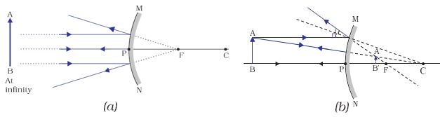
Figure 10.8 Formation of the image by a convex mirror
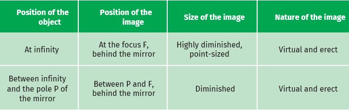
The results are summarised in Table 10.2.
Table 10.2 Nature, position, and relative size of the image formed by a convex mirror
You have so far studied the image formation by a plane mirror, a concave mirror, and a convex mirror. Which of these mirrors will give the full image of a large object? Let us explore through an Activity.
Activity 10.6
Observe the image of a distant object, say a distant tree, in a plane mirror.
Could you see a full-length image?
Try with plane mirrors of different sizes. Did you see the entire object in the image?
Repeat this Activity with a concave mirror. Did the mirror show a full-length image of the object?
Now try using a convex mirror. Did you succeed? Explain your observations with reason.
You can see a full-length image of a tall building/tree in a small convex mirror. One such mirror is fitted in a wall of Agra Fort facing the Taj Mahal. If you visit the Agra Fort, try to observe the full image of the Taj Mahal. To view distinctly, you should stand suitably at the terrace adjoining the wall.
Uses of convex mirrors
Convex mirrors are commonly used as rear -view (wing) mirrors in vehicles. These mirrors are fitted on the sides of the vehicle, enabling the driver to see traffic behind him/her to facilitate safe driving. Convex mirrors are preferred because they always give an erect, though diminished, image. Also, they have a wider field of view as they are curved outwards. Thus, convex mirrors enable the driver to view a much larger area than would be possible with a plane mirror.
Reference: This topic is taken from NCERT Text Book